Hi jacc,
i will do some pictures when i’m back home. You don’t have to unscrew anything unless you want to release the pcb from the whole unit.
Hi jacc,
i will do some pictures when i’m back home. You don’t have to unscrew anything unless you want to release the pcb from the whole unit.
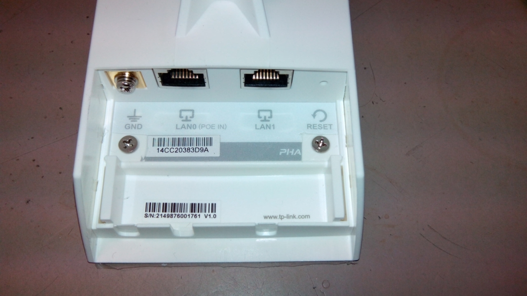
Open the connectors lid.
then peel off the internal label (with MAC address printed on). Do this preferably with (small) sharp knife.
Below you will find 2 PZ3 sized screws. remove them and pull out the inner frame, just straight out, no further hinges/clips to be cared about.
do i have to worry about the fact that i dont have released any screw to pull out the inner frame? ![]()
Thank you. I found the screws under the label. I actually saw it when I used a bright torchlight to shine the router to look for the hinges, but couldn’t confirm it until the help from you guys. I finally managed to open it easily with no force at all. Time for modding ;). Any one thought of upgrading the router with a Semiconductor RF switch , to switch between external and internal antenna? If yes let me know I might have an idea on how to do it.
It looks like you just pulled so hard that you killed the housing. (the counterparts for the screws just shered off…)


![]()
![]()
anyway, it fits perfectly
I was happy to read at the current end of this thread that this device has screws under the label. I was almost reaching out for a saw to open the case.
Adorfer, could you please add a picture of these screws to your collections of photo’s on the first page? That would save others a lot of frustrations and even injuries ![]()
I’d hoped to place a picture here but it seems I cannot do that since I’m a brand-new member.
[edit] Now that I’ve reached the state of ‚basic user‘ I was able to add the picture.
Tnx

I have completed the modifications thanks to everyone here. Let me try to post some pictures. P.s. the solder that they used for the product is lead free, it was almost impossible to melt! I was using both temperature controlled heat air gun and soldering gun at 480 deg Celsius but was still unable to make the solder melt and flow… So please take note of this.
Edit: I cannot post pictures too, it says I am a new user…
Just post the URL without the http, a moderator will fix it.
Sorry for the incovenience.
Moin!
Auf openwrt.org bin ich auf dieses Script gestoßen.
#!/bin/sh
cd /sys/class/gpio
echo 20 > export; echo out >gpio20/direction
echo 1 > gpio20/value
Wo muss ich das hinterlegen das es auch bei jedem Neustart des Knoten auch ausgeführt wird?
In der /etc/rc.local vor der Zeile exit 0
Da kann ich es aufrufen. Und wo lege ich das Script an sich ab in welches Verzeichnis, so das es auch nach nem Reboot wieder verfügbar ist?
Die von dir genannten Zeilen kannst du einfach in die rc.local eintragen. Ein zusätzöicher VErweis auf ein extra Skript ist nicht notwendig. Falls es doch so sein soll, kannst du dir den Ort aussuchen. Irgendwo in /etc/ würde ich es ablegen.
Du schreibst das Script in die /etc/rc.local
etwa
echo 20 > /sys/class/gpio/export
echo out > /sys/class/gpio/gpio20/direction
echo 1 > /sys/class/gpio/gpio20/value
Das schaltet auf den CPEn den POE Passthrough an, oder?
Danke! Funktioniert bestens. Ne CPE210 versorgt jetzt ne LocoM2 mit. Werde es zwar nach Updates neu setzen müssen, aber da die Installation bei mir zuhause ist, ist das kein Problem.
So, ich glaube mein Setup ist jetzt i.O.
Der Plan war an den CPE210 eine LocoM2 anbinden und mit vom CPE210 mit Strom versorgen lassen. Es sollte MESH on WAN verwendet werden.
Mein erster Ansatz die beiden Interfaces eth0.1 und eth0.2 der CPE210 gemeinsam in die Bridge br-wan zu setzen hat zwar irgendwie funktioniert, aber sowohl Clients und auch der Zugriff auf die CPE210 wollte nicht so recht mehr klappen danach. Auch erschien die LocoM2 nicht mehr in der Karte.
Mein Verdacht war das das Software Bridging der Übeltäter ist und habe mir gedacht, warum in Software switchen wenn du doch auch in Hardware switchen kannst. Also folgendes gemacht:
uci delete network.@switch_vlan[1]
uci set network.@switch_vlan[0].ports=‚0t 4 5‘
uci commit network
Ich habe also das Client VLAN gelöscht und den Switch Port mit ins verbliebene VLAN hinzugefügt. Damit sind beide Ports jetzt WAN.
Mesh on WAN hatte ich schon im Configmodus eingeschaltet und den Code zum POE Pass Through einschalten wie oben von den netten Menschen vorgeschlagen in /etc/rc.local eingetragen. Was wunderbar funktioniert.
Da das ganze nicht Update Fest ist habe ich auf der CPE210 Autoupdate deaktiviert. So das ich hier zwar jetzt immer manuell eingreifen muss wenn Updates anstehen, die obigen Config Schritte sind aber schnell mit Copy und Paste durchzuführen in einer SSH Session.
Wie lang ist das Kabel? Welcher Querschnitt?
Uptime der CPE210 noch normal?
Das Kabel zur CPE210 ist ein 10m langes flaches Ethernet Kabel was durch ein Fenster führt. Die LocoM2 und die CPE210 sind ca. 1,8m voneinander entfernt an meinem Balkon Geländer befestigt. Verbunden durch ein 2m langes Ethernet Kabel. Versatz zueinander sind geschätzt 120-130 Grad. Bei der größt möglichen Entfernung, begrenzt durch Bebauung, von ca. 150m Abstand zur CPE210 erhalte ich noch ein Signal von -75 dBm und 6/2 Mbit Durchsatz. Uptime beider Geräte ist jetzt gut 15 Stunden. Load Average bei Loco und CPE liegt zur Zeit bei 0.42 bzw. 0.40. TQ zwischen ihnen und dem WDR4300 der als Offloader dient ist 100.
TP-Link hat den Chipsatz AR9350 bei den neueren Modellen gegen den AR9344 getauscht. Der AR9350 ist quasi der AR9344 für industrielle Anwendungen, er ist also etwas gütiger was den Temperaturbereich usw. angeht. Ich denke aber nicht, dass das spürbare Auswirkungen haben sollte.